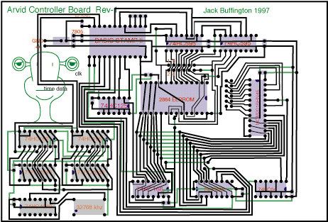
Most of the stuff on this page is out of date and not what I ended up doing but I kept it here because perhaps it could help someone else even though what I have presented here is a terribly backwards way of doing what I wanted. This board would have been VERY slow because of the processor that I had chosen. I have some newer information at the bottom of the page.

At first I was unsure about posting the design for Arvid's controller board since it is my own design that anyone could copy if I posted it. However, I am getting better at this stuff and can now design a better board with fewer components. The board itself is a double sided board. I have tested most of the pieces on a breadboard, but have had some trouble getting my circut board made. I have learned about a different method of making them and should have it done in a few weeks. My only worry about this board is that it may not be able to keep updating all of the servos fast enough. To solve that, I may just put in a few header pins so that I can use one clock for two boards. That will keep them in sync.
A general description of the board is as follows. The bottom left group of chips is the clock unit. I put this in so that I could have my animatronic keep in sync with whatever may be going on around it. It consists of the four pin 32768 Khz clock which is divided down to a useful number by the bottom left 74HC4040. One of its outputs is lead into the one of the two other 74HC4040's which count the pulses. They are my clock output. I then can read the current state of the counter using the 74HC166's.
The Basic stamp itself is the top left chip. Next to that are two 74HC595's which are serial in - paralel out shift registers. I use these to give addresses to my RAM and ROM. The next row down has a 74HC125 which is a three state bus. Next is the EEPROM. It is an 8K 2864. Finally there is the RAM. It is a 2K 2016 RAM. I will only use a handful of bytes in it since the Basic stamp does not quite have enough. (32bytes)
The bottom row contains a 74HC166 which is a paralel in serial out shift register. It sends the data from the RAM or ROM to the Basic Stamp. Next over is another 74HC595. Its purpose is to give data to the Ram when the stamp wants to write to it. . Finally there is a 74HC04 which is a bunch of not gates. I just use one of them to allow me to select which chip I want to be enabled RAM/ROM. I make no guarantee about if this is functional or not, but I suspect that it is. Really this board could be used to beef up the stamp, but it will surely take a lot of the stamp's program memory just to be able to use this board. If you are confident enough, I would recommend that rather than using this board, you just move on up to a PIC processor. If you use one of their 17C series, you have all of this functionality on one chip or you could use a 16C series chip with a serial EEPROM to be equivalent. Still, I am going to try to build this board so keep checking back from time to time to see what has come of it.
The method to control Arvid that I ended up using is a PC based program that I wrote. It can animate up to 8 servos as it is written now. It works with Scott Edwards's mini SSC II. This is a pretty nice servo controller. I am thinking that I would like to make a servo controller of my own because I am feeling constrained by the baud rate that his boards use. For the type of movement that I am looking to make, I would like to be able to update the requested position of the servo fairly often. Unfortunately, his controllers use a baud rate of 2400 or 9600. 9600 is pretty good but you can't have too many servos in the chain before the update rate has to drop to acomidate them. Of course another reason that I would build my own controller would be the cost. I could make a controller for a lot less than the $50 that his boards cost. Building my own controller will be a good project someday.
I will be posting information about my servo control software shortly if I don't have it online already.
|

